M. Ducceschi, S. Bilbao and C. Webb
Non-iterative schemes for the simulation of nonlinear audio circuits
24th Conference of Digital Audio Effects (DAFx-20in21)
It is possible to solve nonlinear state-space models non-iteratively, via linearly-implicit schemes. The update requires at most the solution of one linear system, thus sidestepping the machinery of iterative methods (including design choices such as the maximum number of iterations and tolerance). The schemes can be constructed so to satisfy increasing orders of accuracy, (p=1:4). In particular, a first-order accurate scheme can be constructed, depending on a free parameter. The scheme is unconditionally stable, therefore guaranteeing passivity. The free parameter controls the amount of low-pass filtering induced by the scheme, reducing aliasing. Here, the non-iterative schemes are compared to two classic designs: the trapezoid and midpoint methods.
Diode Clipper
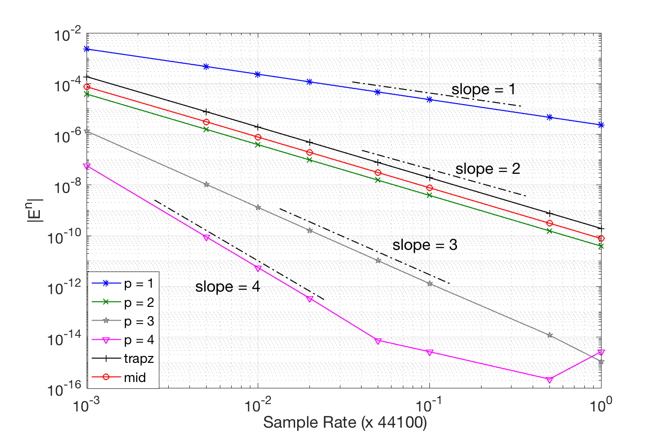
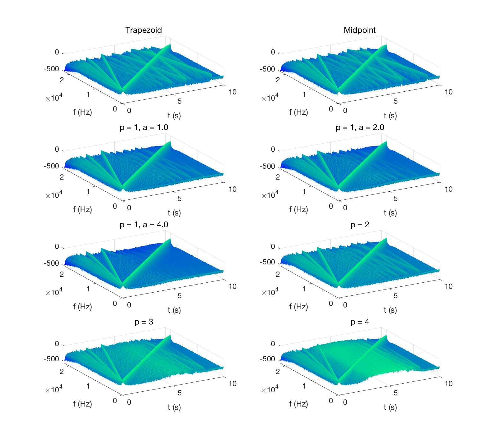
Outside of its relevance in the context of virtual-analog simulation, the diode clipper is particularly interesting from a numerical stand-point. Explicit numerical designs (such as e.g. Forward Euler, orthe Runge-Kutta RK4 scheme) are known to fail here, unless the time step is chosen to very small values compared to the time scales of the computed solution. The differential equation is stiff in this case, as the exponentially-unbounded nonlinearity accounts for a fast variation in the transients of the computed solution. Linear sine sweeps are passed through the diode clipper, simulated using the schemes described above. Note that higher-order scheme have worse aliasing than lower-order ones. The free parameter a in the p = 1 scheme can be tuned to effectively reduce aliasing. Matlab sample code is available here.
| Input | |
| Trapezoid | |
| Midpoint | |
| p = 1, a = 1 | |
| p = 1, a = 2 | |
| p = 1, a = 4 | |
| p = 2 | |
| p = 3 | |
| p = 4 |
Ring Modulator
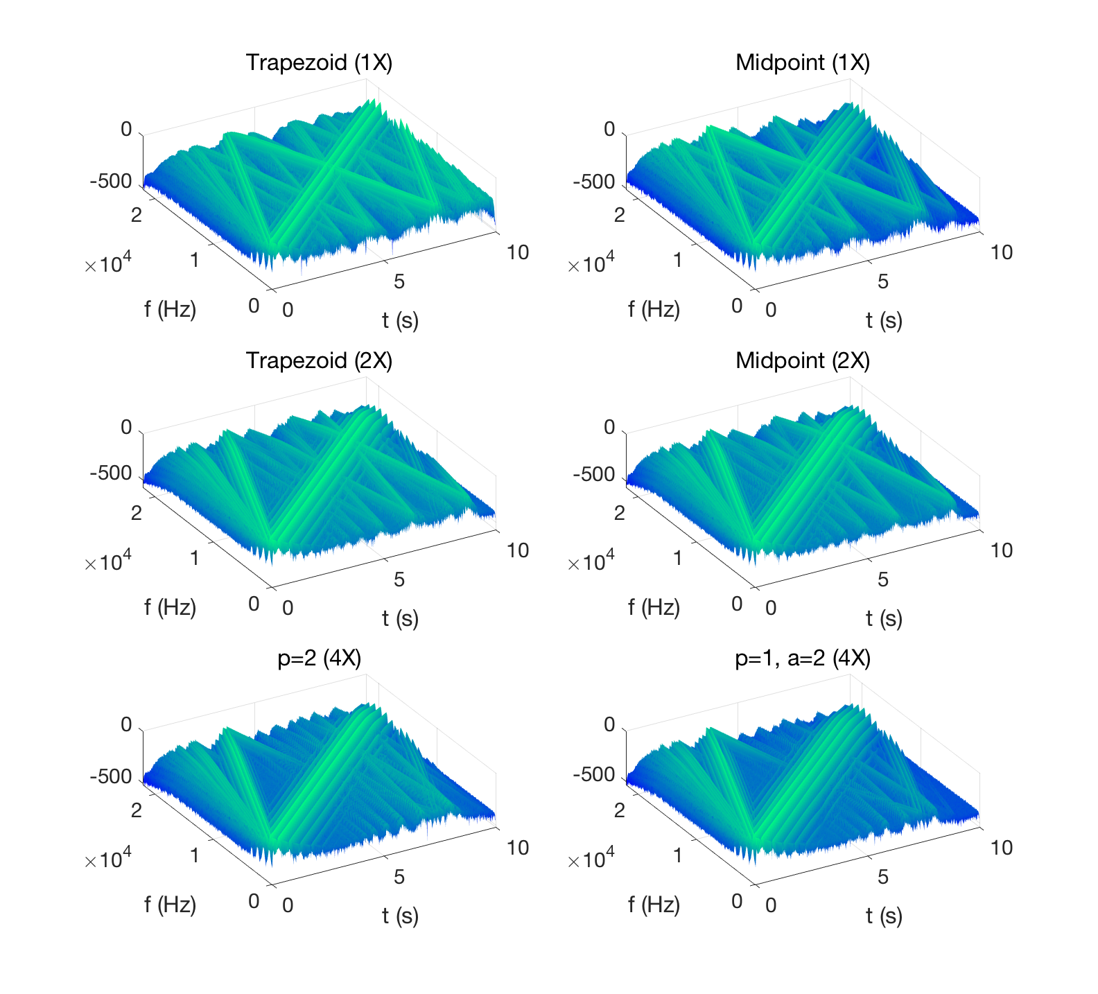
The ring modulator is expressed as a system of nonlinear equations. Extensions of the scalar case above are possible. Here are the results from two sine sweeps, using different carrier frequencies.
| Input (modulator) | |
| Trapezoid (1X) | |
| Trapezoid (2X) | |
| Midpoint (1X) | |
| Midpoint (2X) | |
| p = 1, a = 2 | |
| p = 2 |
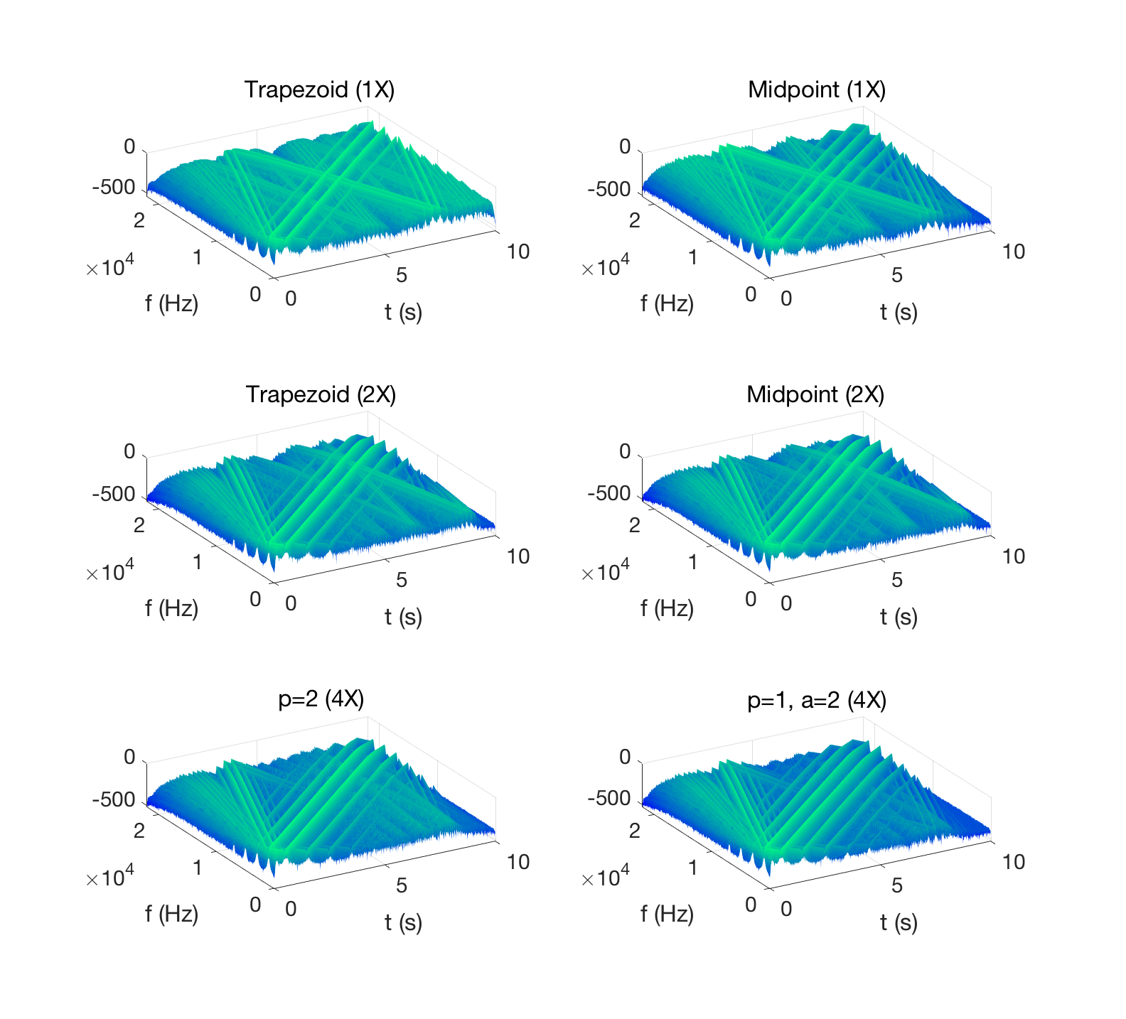
| Input (modulator) | |
| Trapezoid (1X) | |
| Trapezoid (2X) | |
| Midpoint (1X) | |
| Midpoint (2X) | |
| p = 1, a = 2 | |
| p = 2 |
Compute Times
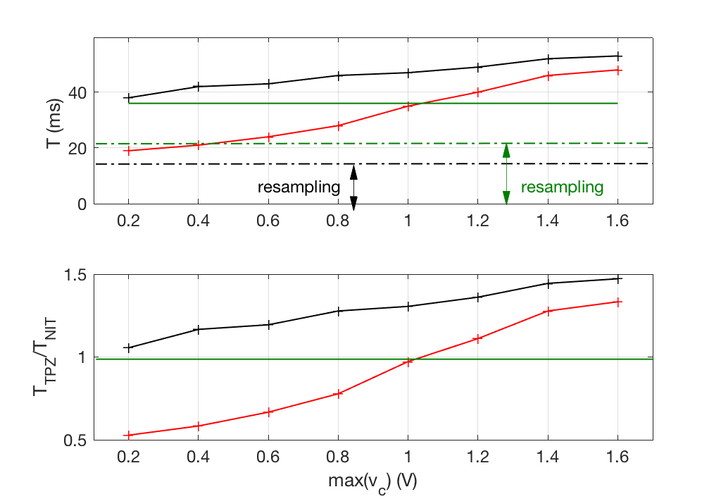
Below are the ring modulator compute times in C++ for 1 second of output. The non-iterative schemes work at a fixed cost, comparable to that of the trapezoid method for average input voltage amplitudes.
